Introduction
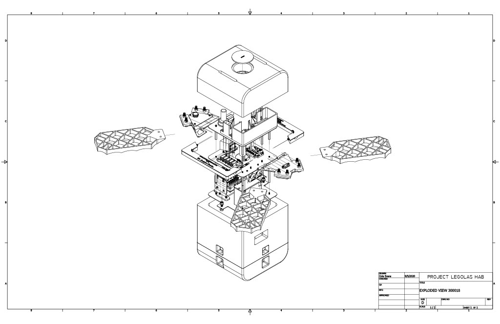
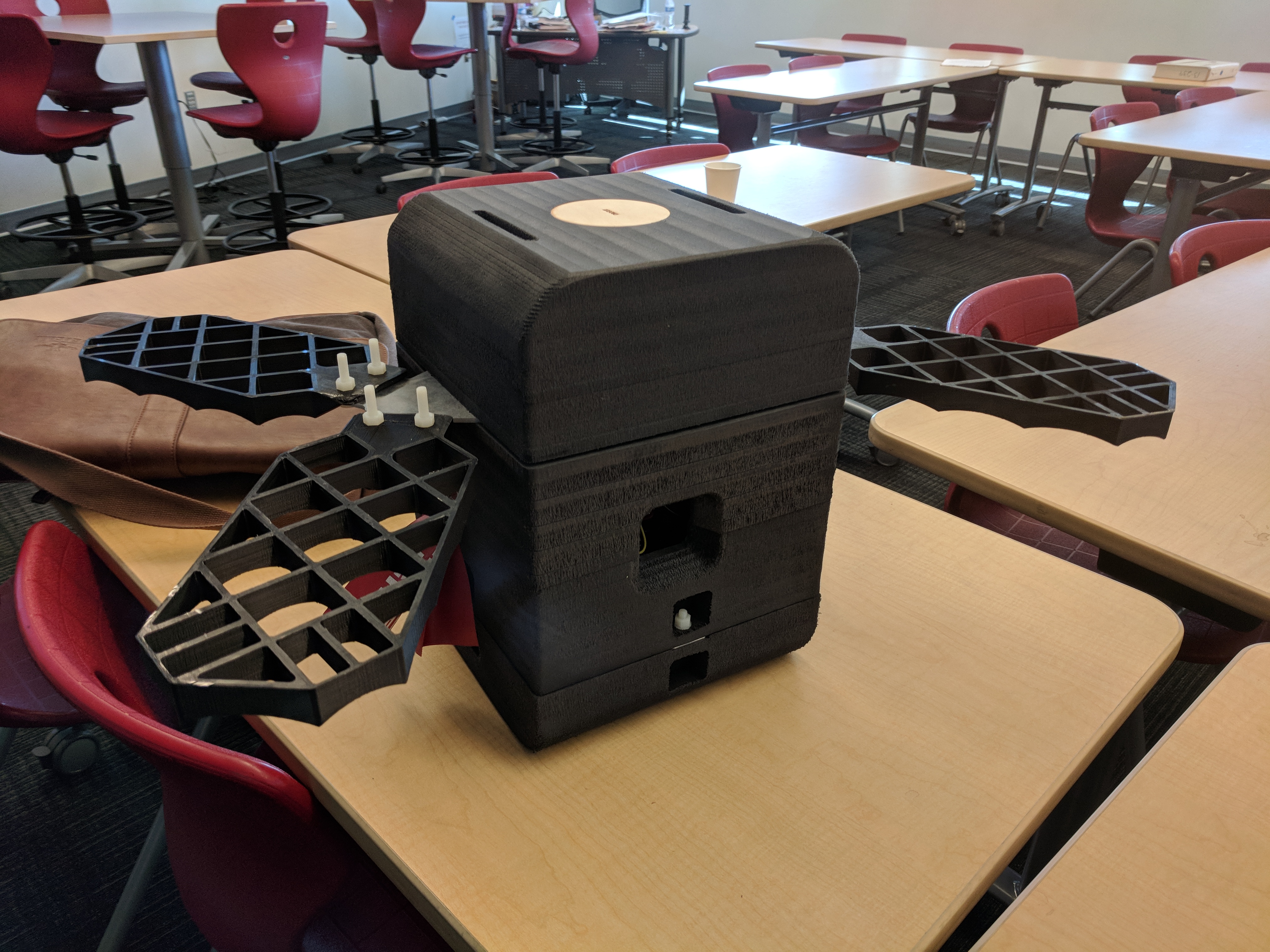
Project Legolas is a high altitude balloon payload I’ve been working on for the past couple of years. It’s designed to detach from the balloon once it pops at approximately 120,000 feet and freefall until parachute deployment at 2500 feet. This provides payloads with clean microgravity, at a much lower cost than a sounding rocket or even a drop tower. The design has gone through several iterations and design upgrades, with the first flight of the V5.0 planned in May 2021. My design responsibilities include the mechanical and electrical design, along with leading assembly test and flight operations.
Table of Contents
- Introduction
- Intial Designs
- 2.0 Redesign
- Design Overview
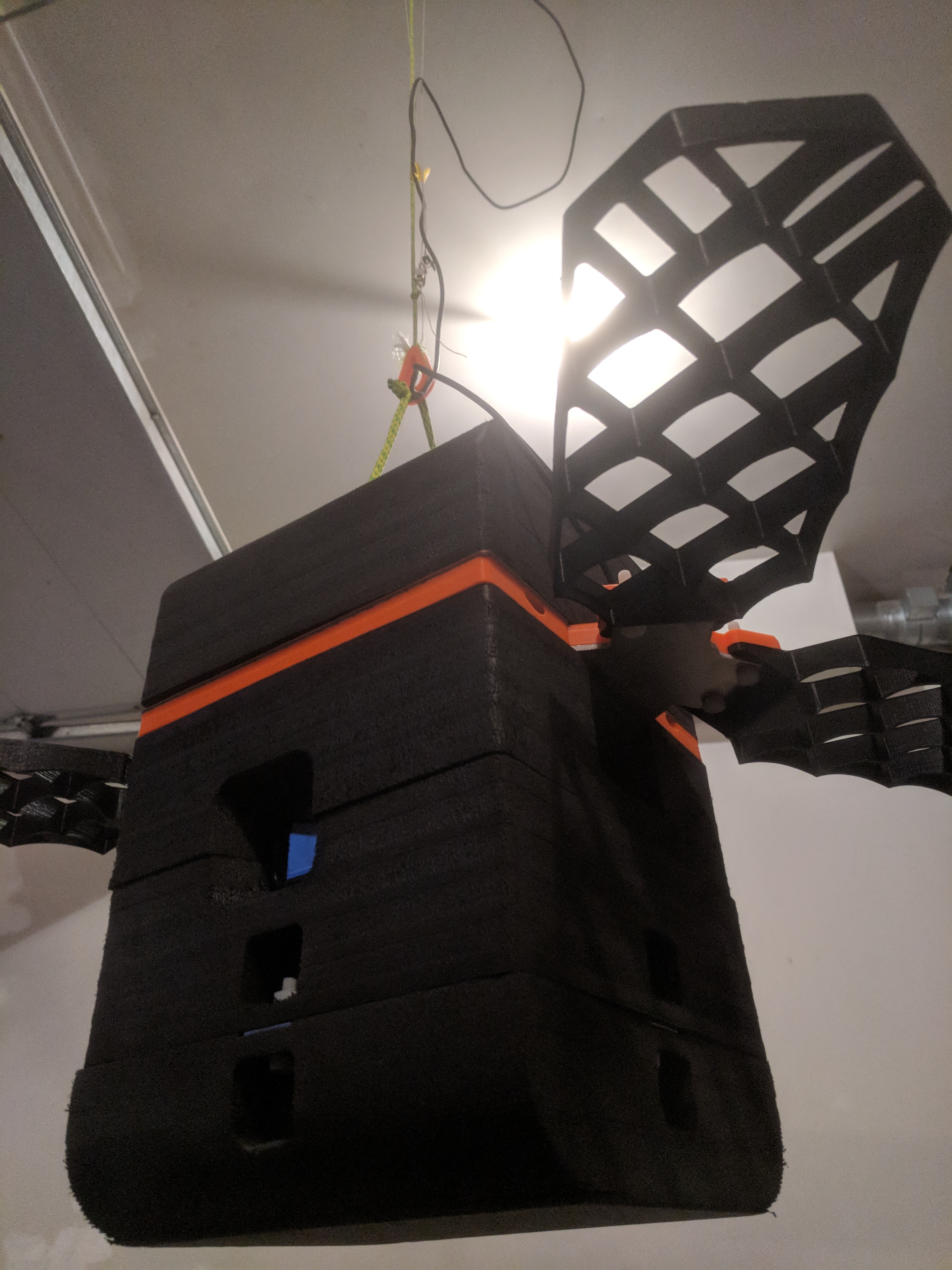
- Structure and Outer Shell
- Cutdown and Parachute System
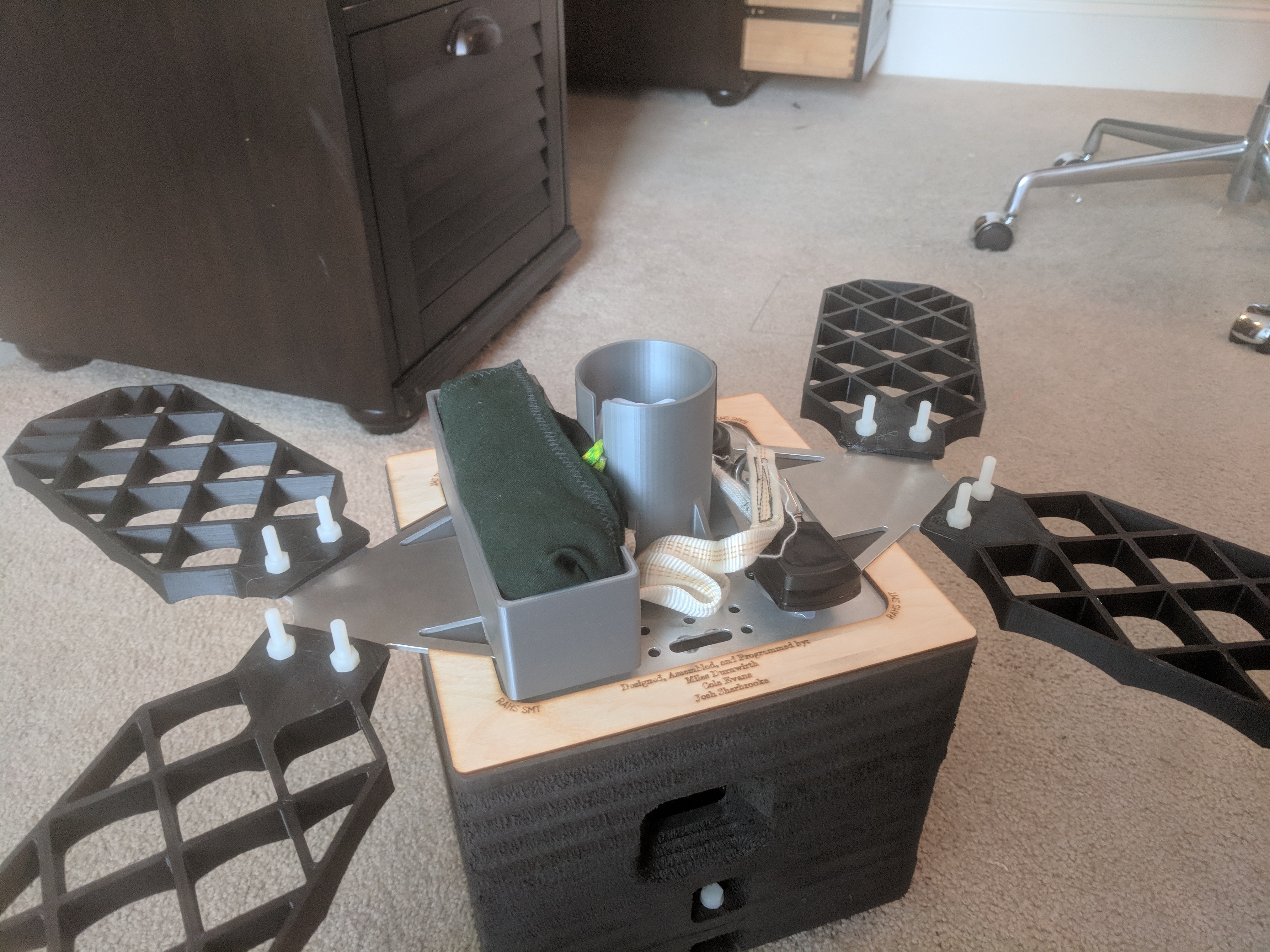
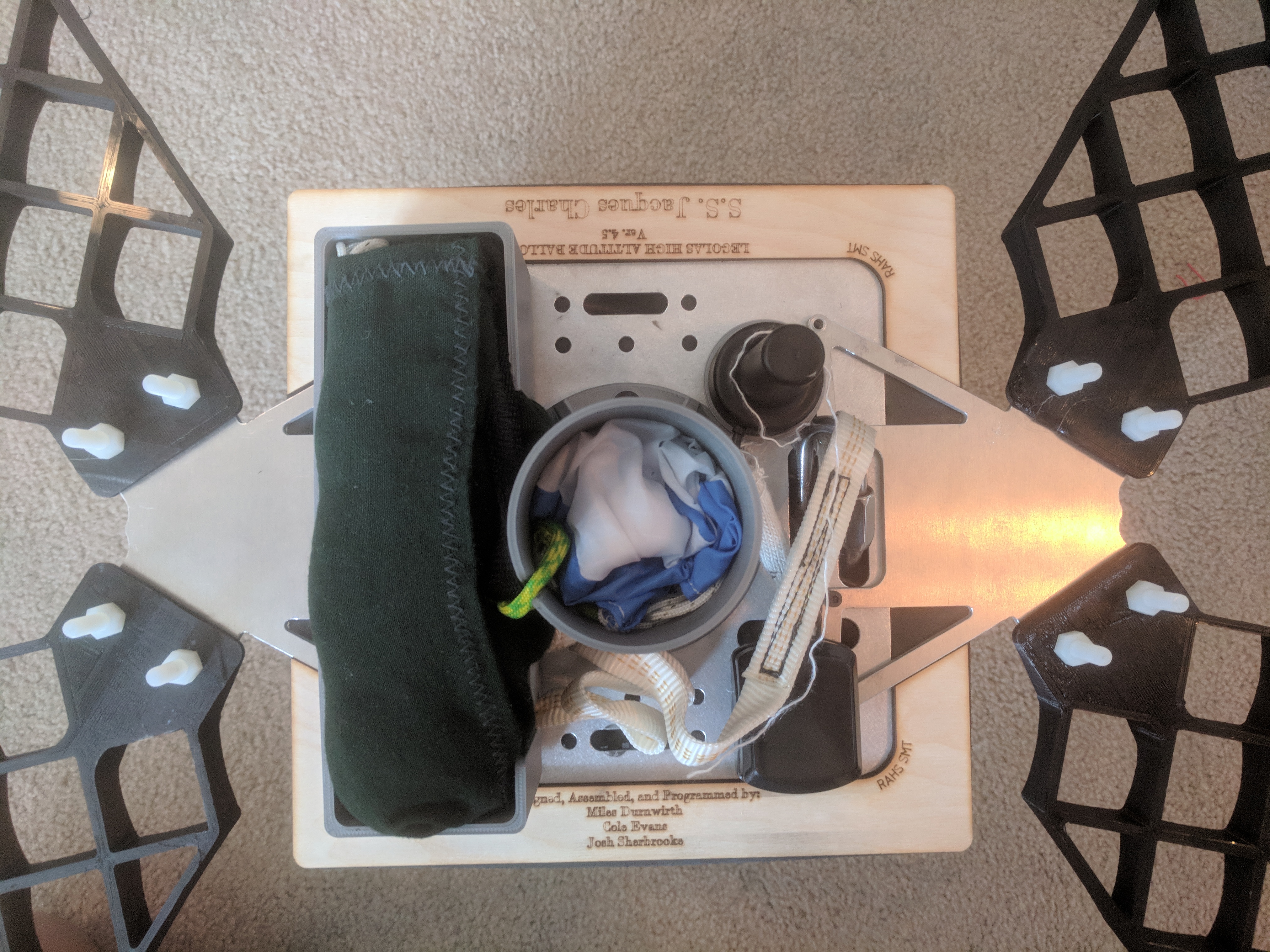
- Grid Fins
- Avionics
- Flight Software
- Pyro Systems
- Windtunnel Testing
- Helicopter Drop Test
- Drop Test Results
- Avionics Block 2 Upgrade
- Current Status
Intial Designs
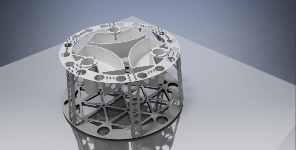
The initial design (V1.0) was much larger than the current version. It was 3.3ft in diameter conical capsule, with a waterjet aluminium 6061-T6 subframe and a vacuformed outer shell. Components were manufactured for this design, but it was ultimately downscaled to the current iteration.
2.0 Redesign
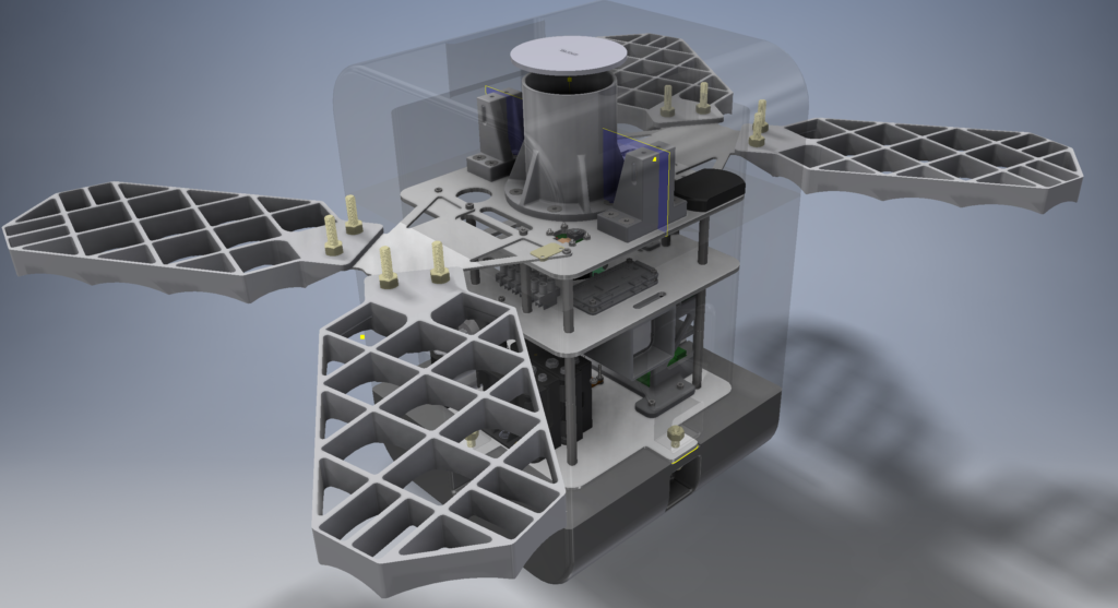
The decision was made to downscale the design to a smaller form factor and redesign the parachute deployment sequence, payload size, outer shell, and pyrotechnic system. This design evolved though testing and evaluation from version 2 through version 4.5, which successfully demonstrated the parachute recovery sequence during a helicopter drop test in October 2018.
Design Overview
Several key design requirements of the LEGOLAS system were drafted at the beginning of the design process. Requirements were chosen to address some common failure modes with high altitude balloon payloads and support the intended mission. These include:
- Safety and redundancy
- Reliable recovery/retrieval
- Reusability/improvability
- Easy payload integration
They payload flies under a FAA CFR part 101 waiver for Unmanned Free Balloons. Because of this, all systems must be demonstrated to ensure safety to the general public throughout the flight. Disconnecting the primary payload from the balloon provides a significant hazard should anything go ary, therefore emphasis was placed on the cutdown and parachute deployment systems, to ensure redundancy during these critical events.
Additionally, tracking and recovery is accomplished with an Iridium satellite phone modem, allowing communication with the payload without direct line-of-sight to a ground station. This allows a cutdown to be remotely commanded from the ground should the need arise.
Structure and Outer Shell
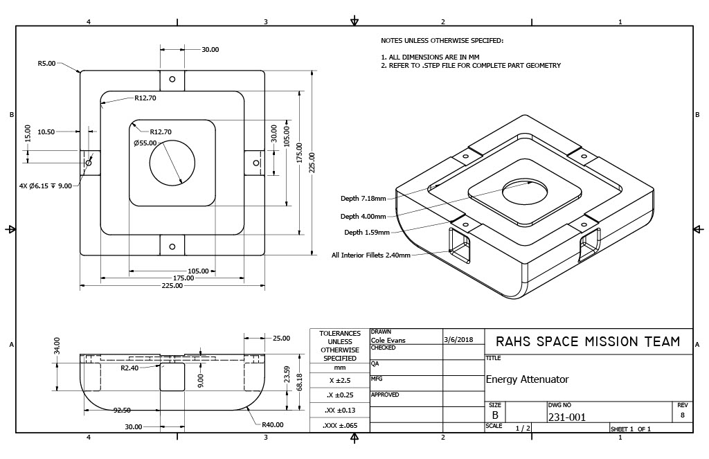
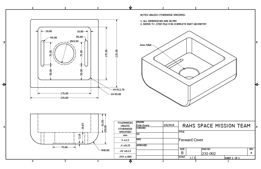
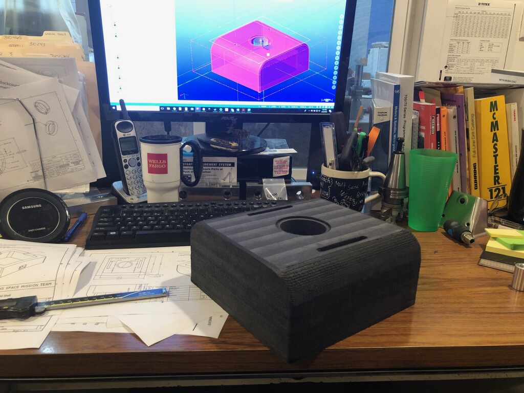
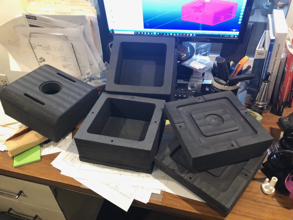
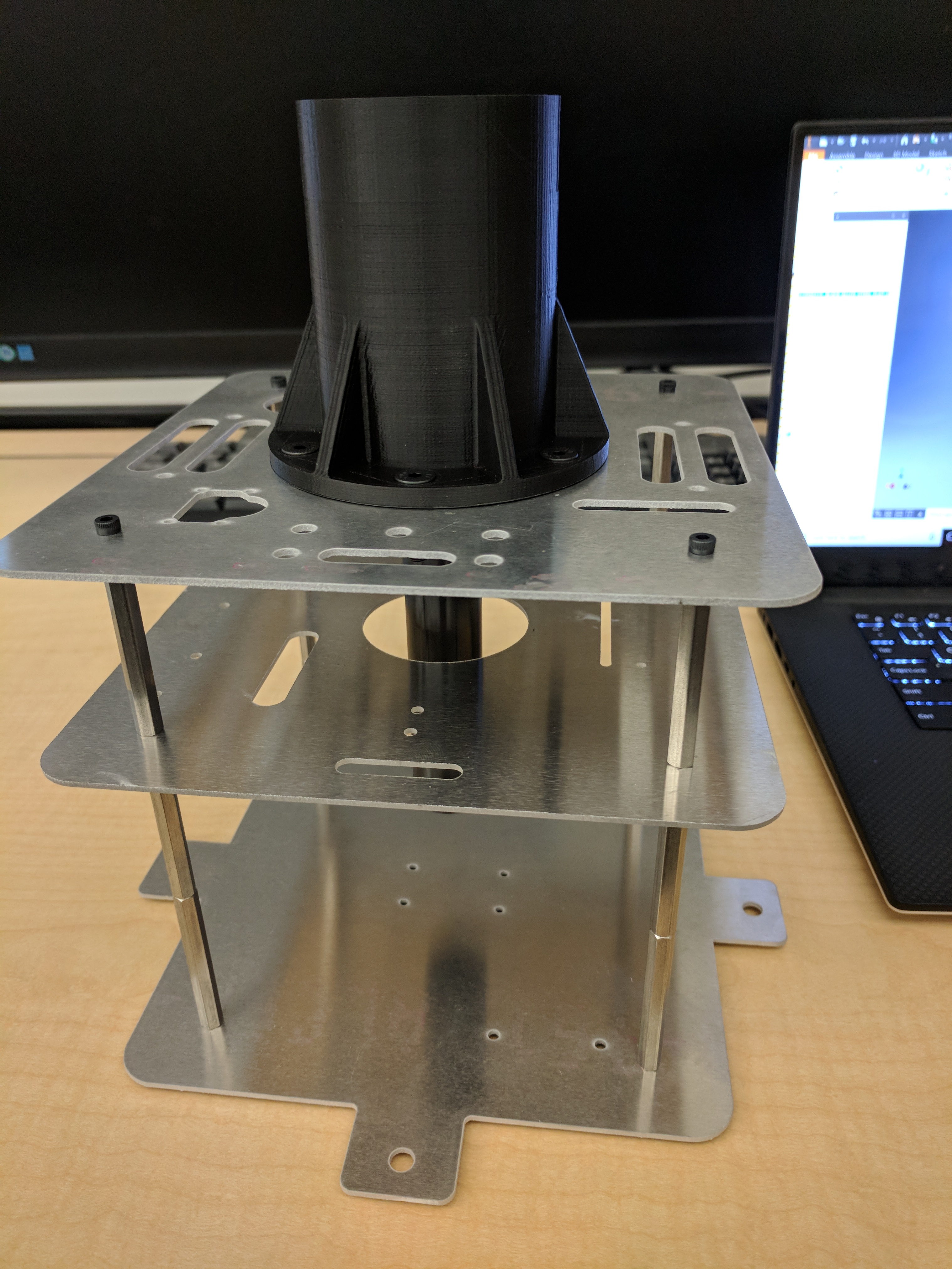
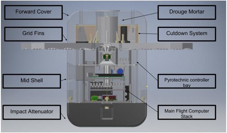
The internal frame consists of 3 waterjet cut 6061-T6 aluminum plates supported by threaded standoffs. The external foam shell provided an interesting challenge. Finding a foam that wouldn’t expand in a vacuum, or deform after landing impact was a difficult process. I eventually settled on XPLE (Cross Linked Polyethylene) foam. XPLE is a closed-cell, fairly dense, water resistant foam. Originally the external shell consisted of three parts: the impact attenuator, mid shell, and top cover. After some discussions with the machine shop, the mid shell was split into two separate halves so that special tooling wasn’t necessary for the internal fillets. The impact attenuator is fastened with nylon shear bolts to prevent damage to the payload in the event of a hard landing due to wind or terrain.
Cutdown and Parachute System
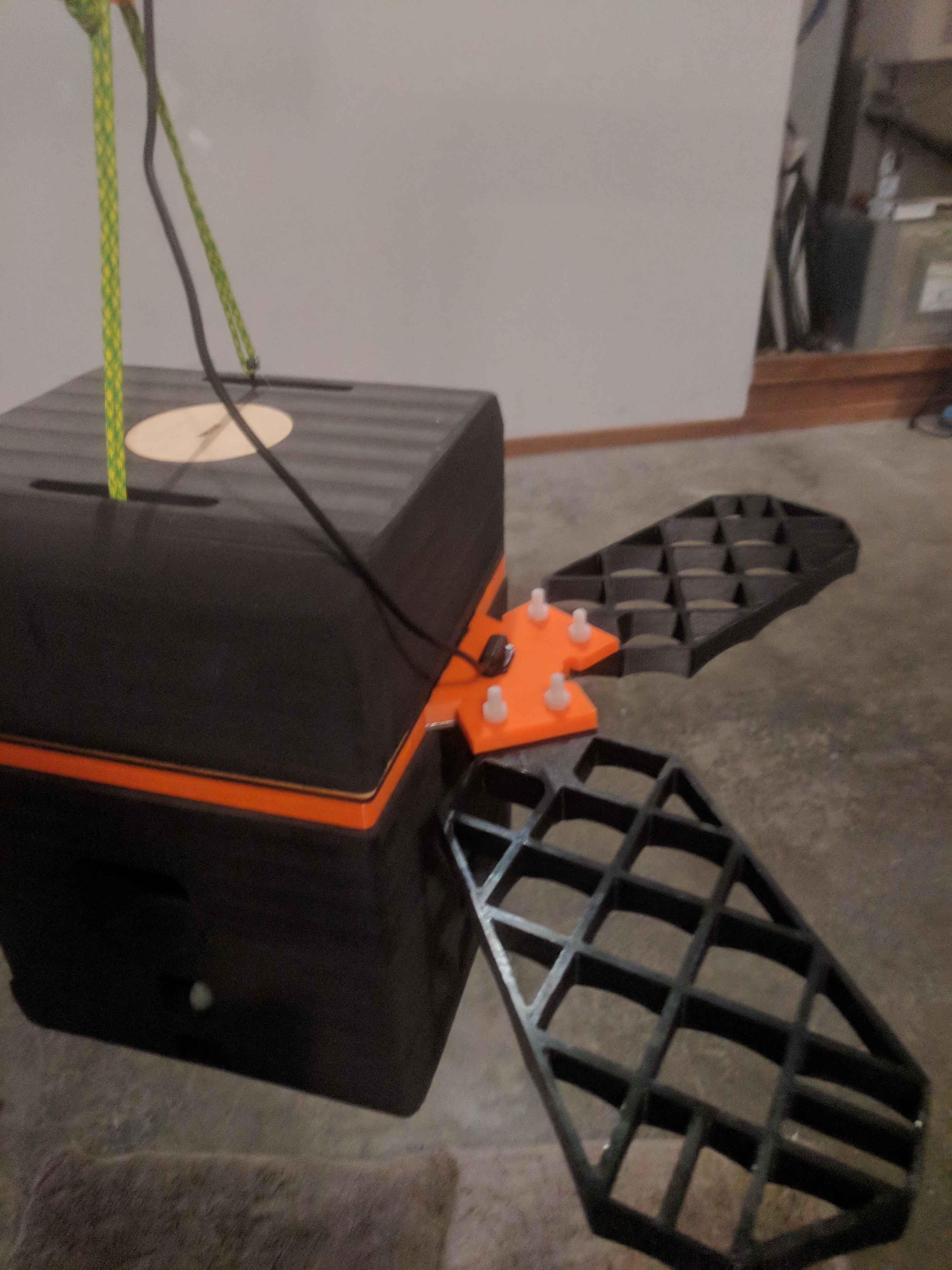
Due to the absolute importance of cutdown occurring, the cutdown system is configured in a quadruple redundant configuration, on two separate relay busses. Black powder Cable Cutters were chosen as the cutdown method. Two mounting points connect the payload to the balloon risers. At the end of each riser line, a cable tie is secured through a dual cable cutter system to a zip tie.
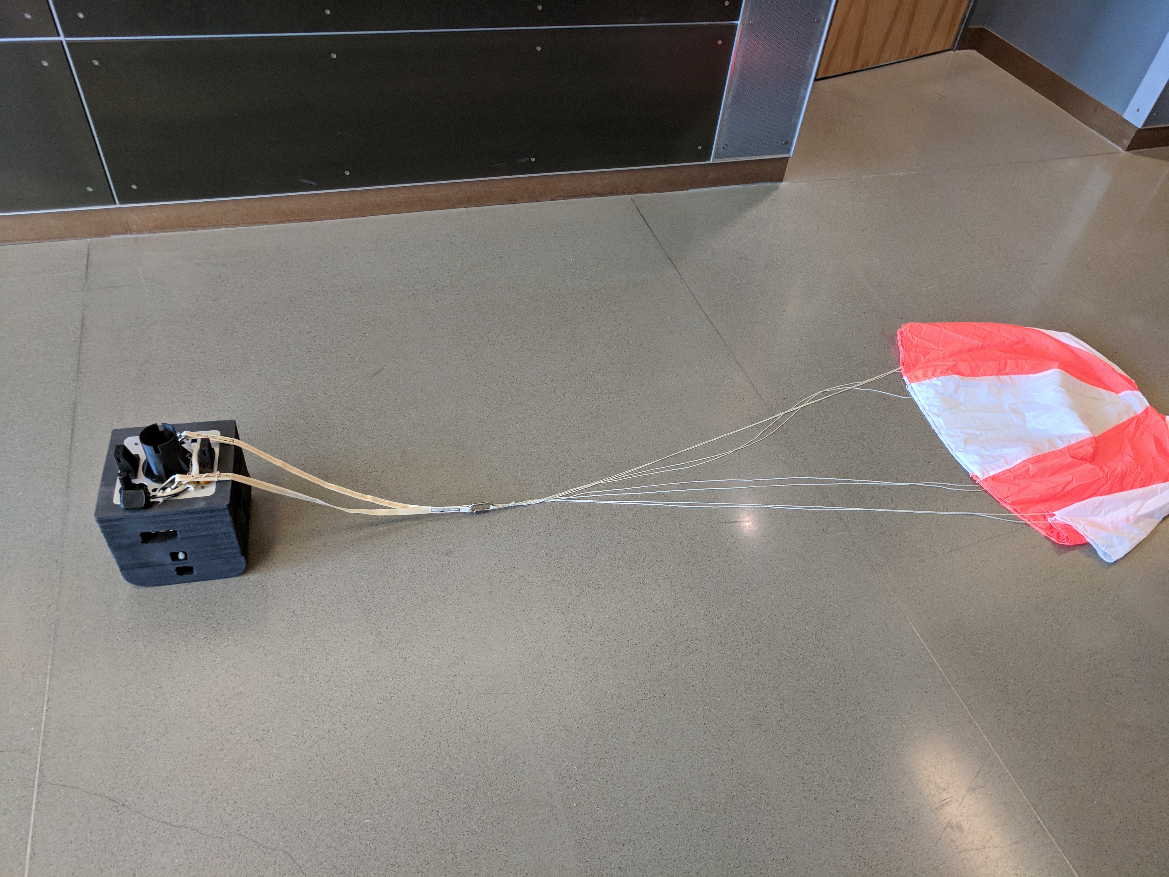
Parachute deployment is accomplished by a CO2 canister, pierced by a pyrotechnic charge. The CO2 system is an off-the-shelf Peregrine Deployment System and has proven to be highly reliable. First, the drogue parachute is fired out of the mortar tube at a sufficient velocity to clear the wake of the vehicle. Once the line snatches, the top cover is pulled off, subsequently deploying the main parachute from the deployment bag.
Grid Fins
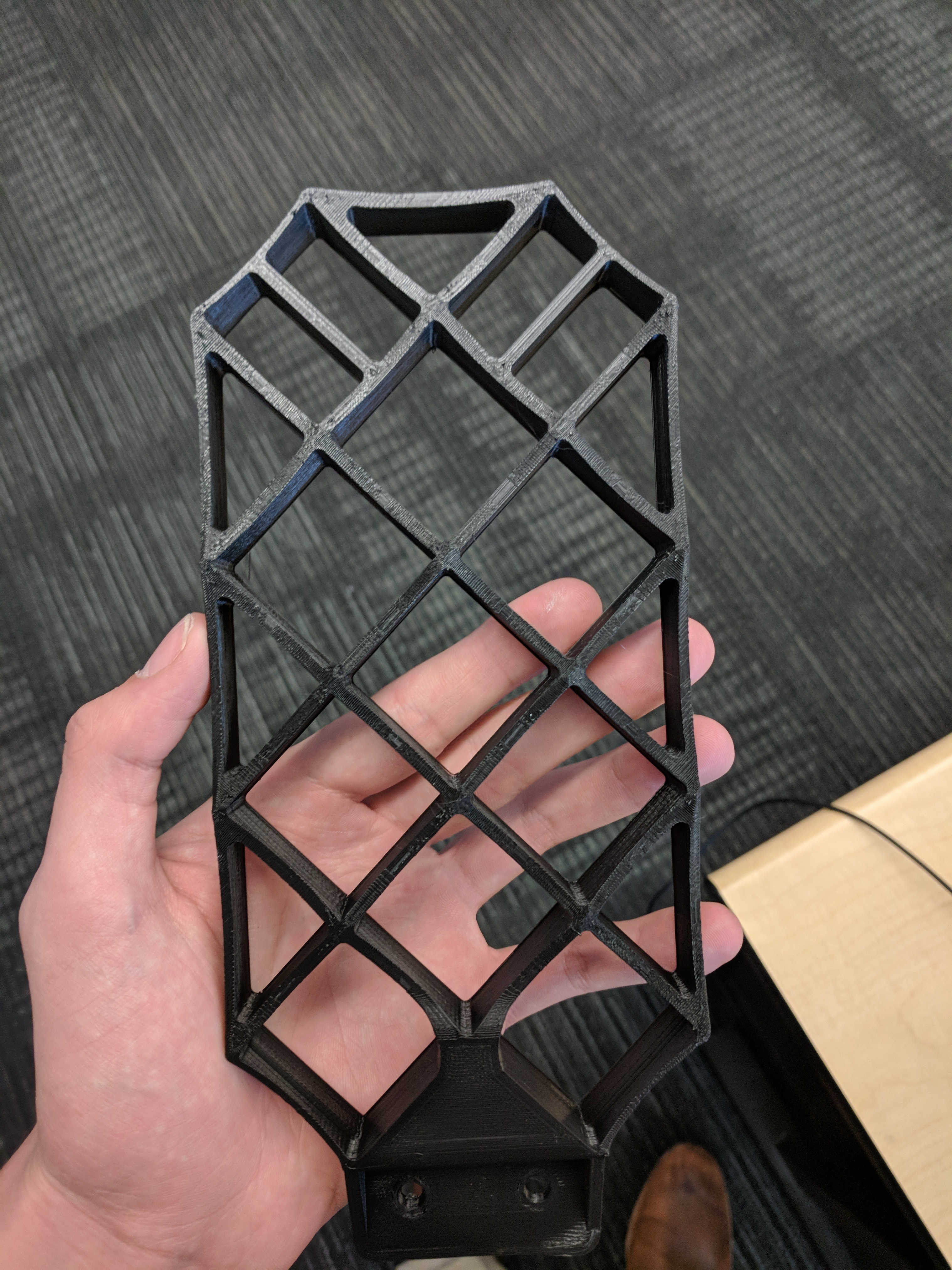
Originally, there was no plan to attempt to stabilize the vehicle during descent. It was later determined from on ground-based testing that a parachute deployment more than 30 degrees past vertical could cause it to tangle with the vehicle or deployment bag. Grid fins were added to provide stabilization during the subsonic portion of the descent.
Avionics
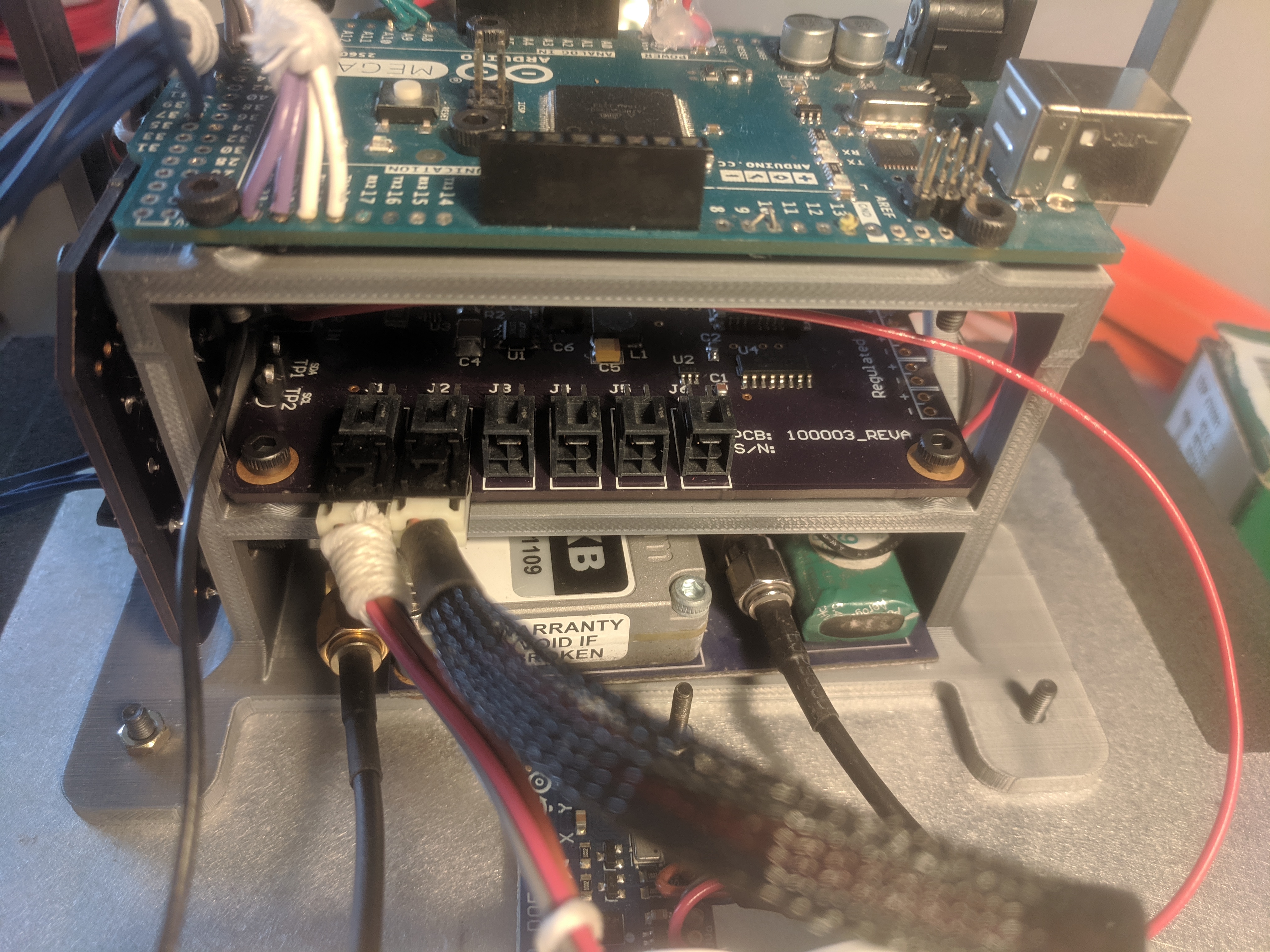
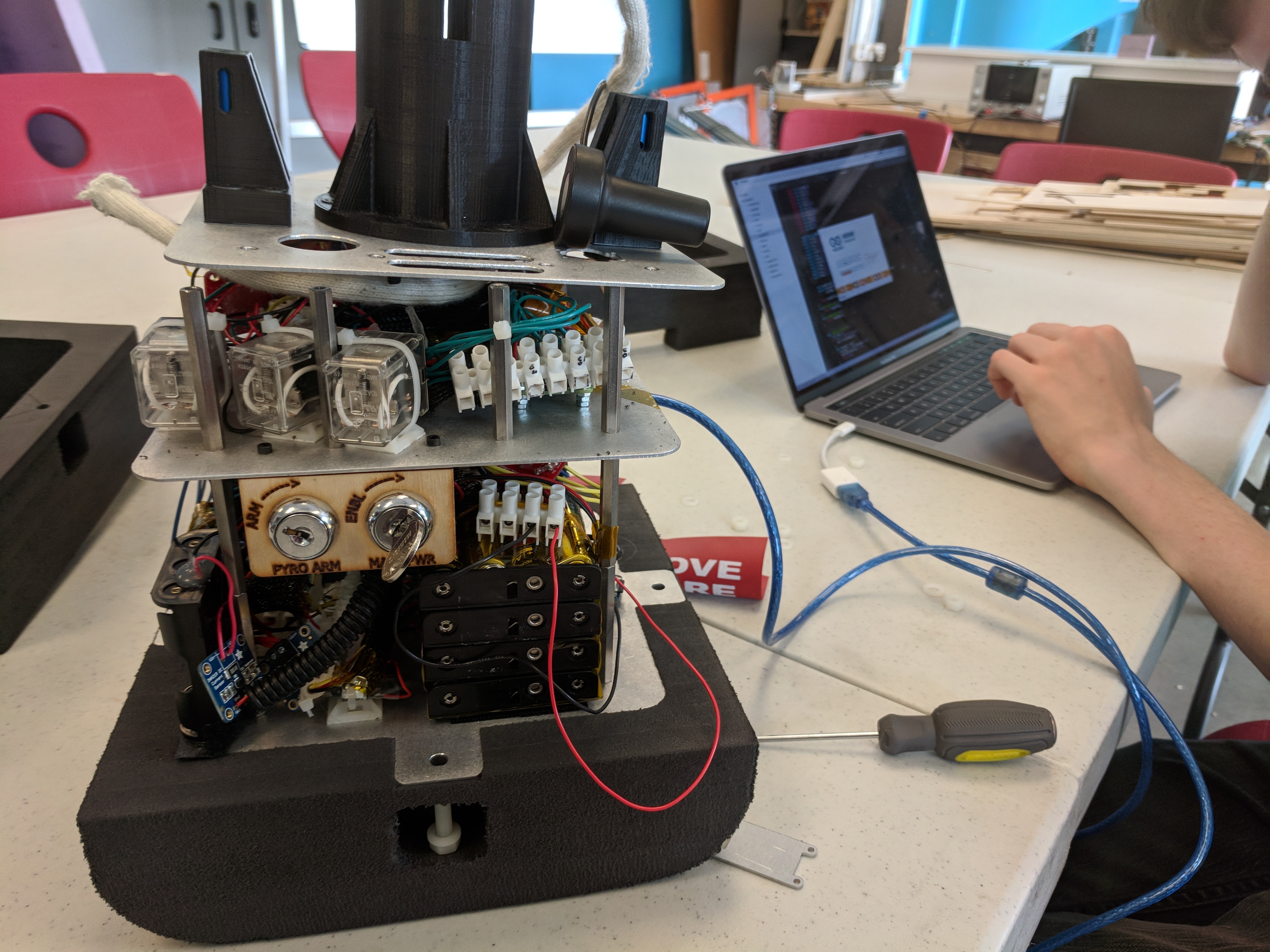
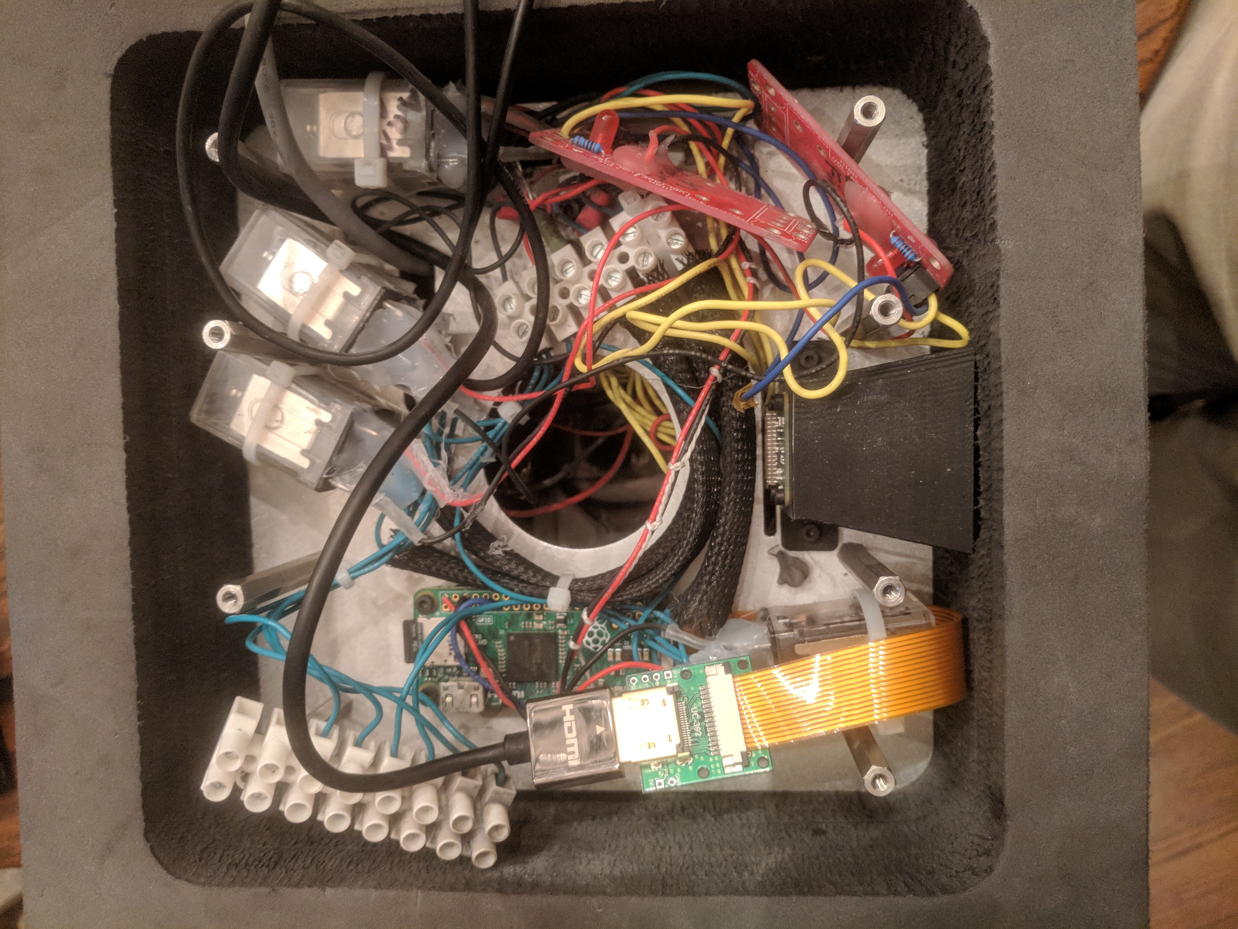
The avionics have gone through several block upgrades, but the core Arduino Mega based flight computer has remained the same. The Main Flight Computer (MFC) is connected to other sensors and pyro relay controllers. The MFC runs a non-blocking queue of timed tasks to update sensor values and perform actuation logic. Essentially, this means that every action to be performed is isolated into a distinct task that cannot affect or disrupt another. The MFC periodically sends data to the Rockblock communications board to be downlinked via the Iridium satellite network, using a callback to ensure that delay in transmission does not affect the rest of the system.
The radio and antenna subsystems allow for telemetry and tracking data to be relayed to the ground crew. The system is designed to facilitate ease of use, as well as redundancy on critical systems. The primary radio system communicates over the Iridium SBD protocol, allowing data to be received regardless of payload location, altitude or orientation.
Data is formatted in CSV format to allow the maximum amount of data to be transmitted within the 360-byte message length limit.
Backup location is transmitted over the APRS network, utilizing the Tracksoar open-source tracker. The Tracksoar is powered by a separate battery pack and operates completely independently from all other avionics.
GPS location is the most critical data, allowing the payload to be recovered after landing. The payload contains two GPS antennas; an active patch antenna for iridium, and a passive patch antenna for the APRS downlink. Both receivers are manufactured UBLOX Max-8Q, which allow for accurate location data up to 50,000 meters.
| Type | TX Frequency | RX Frequency | Power |
| APRS | 144.39 MHz | N/A | 300Mw |
| APRS GPS | N/A | 1.575Ghz | RX Only |
| Iridium Satcom | 1616 MHz | 1626.5 MHz | 1.6W |
| Active Gps | N/A | 1.575Ghz | RX Only |
Flight Software
The MFC Flight software was written by the very talented Josh Sherbrooke and can be viewed on github here.
The basic functions center around a state machine that progresses linearly to prevent major events from happening out of sequence.
Cutdown will be actuated when any of the following cases are true:
- Accelerometer detects freefall: the average of the last 6 recorded acceleration magnitude values (measured at 5 hz) is between -2 and 2 meters/second/second.
- GPS detects freefall: all of the last 3 recorded GPS altitude values are 200 meters or more below the highest recorded altitude.
- Barometer detects freefall: all of the last 3 recorded GPS altitude values are 200 meters or more below the highest recorded altitude.
Parachute deployment occurs when any of the following cases are true:
- Gps Altitude below 762 Meters
- Baro Altitude below 762 Meters
- Backup timer (helicopter drop test only)
Pyro Systems
Pyrotechnics are initiated using dual throw dual pole (DTDP) relays, which ground both power of the pyros to chassis ground when not armed or firing. Below is the first test of the system in 2018.
Windtunnel Testing
After testing and checkout, the payload was approaching flight readiness. I wanted to test the freefall stability and parachute deployment by dropping the payload from a helicopter. This would be a high-risk test, considering it was hard to model the stability of the payload due to its shape and fin design. The team decided that getting some wind tunnel testing data would be helpful in determining the stability characteristics. We reached out to IFLY Seattle, a vertical wind tunnel used to train skydivers. This provided a unique opportunity to test the vehicle in freeflight, in a controlled and incremental way.
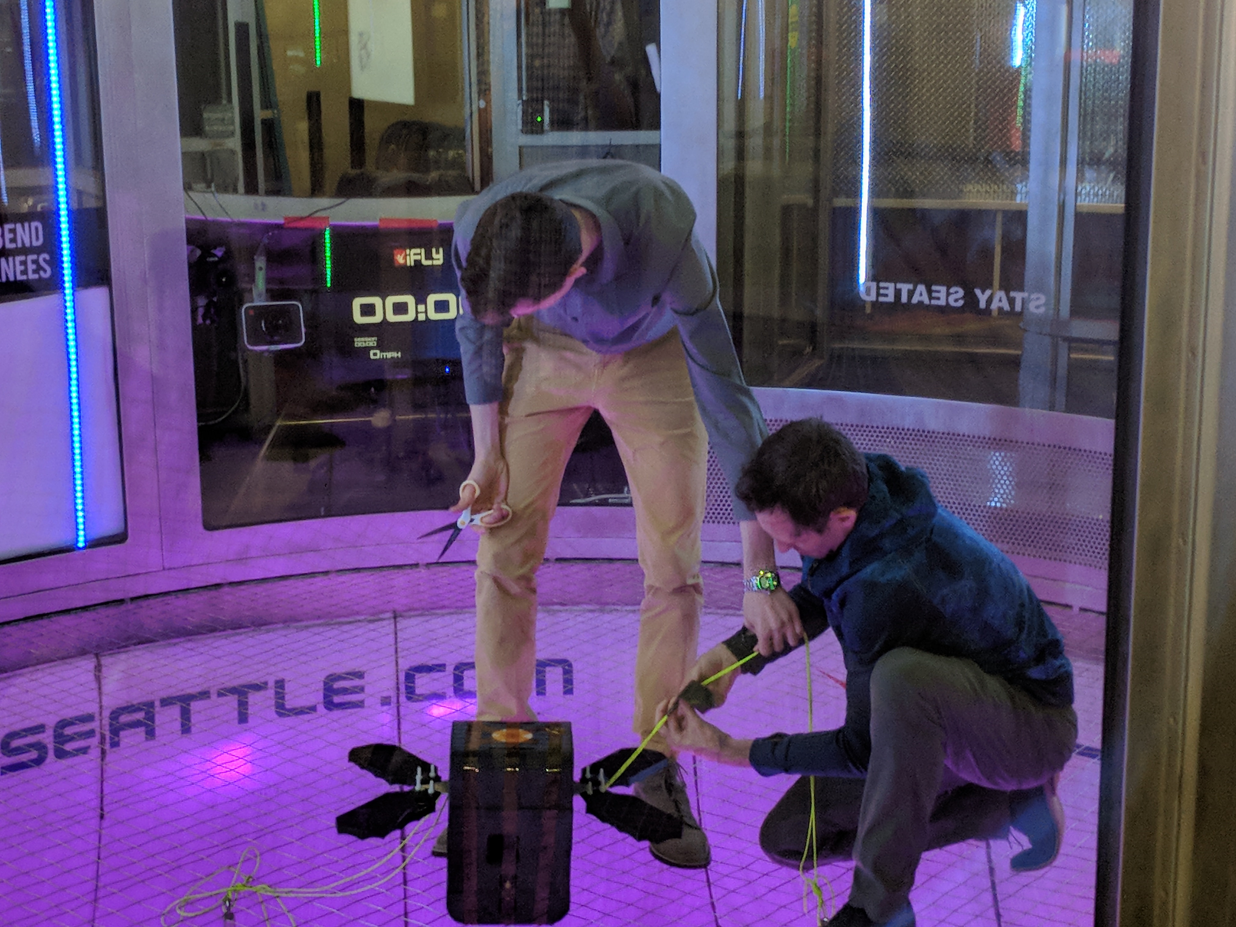
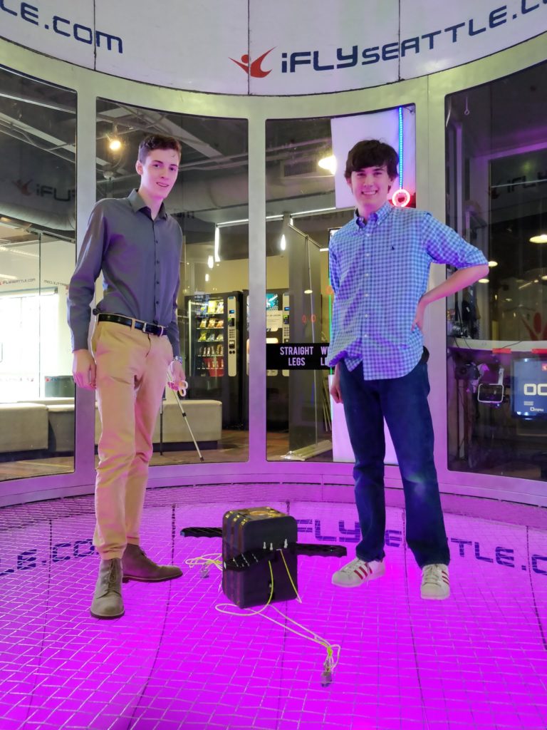
Ifly was very concerned about debris damaging the tunnel. The fans are in the ceiling, so any detached object could present a danger to the system. We were required to tape the top cover, remove the parachute, and attach the payload to the floor netting. This introduced a problem in testing, where the attachment points artificially raised the center of gravity, leading to the payload flipping when it reached the end of the lines. The payload remained powered on during this test and collected enough data to prove the stability in the few seconds it had unencumbered by the tethers.
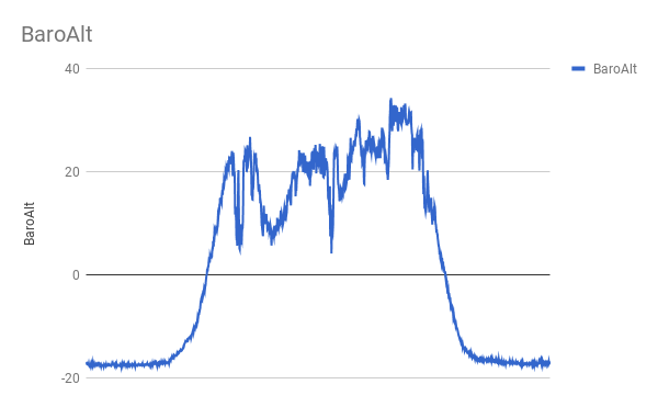
One thing that struck me as interesting was the barometric data recording during the test. The tunnel is essentially a huge venturi, so the air pressure drops as the flow accelerates through the contracting section. This was registered as a fairly large altitude increase in the baro_alt graph.
Helicopter Drop Test
Following the wind tunnel test, we decided that the payload was ready to be dropped from a helicopter to validate the recovery system. This test presented some unique challenges – mainly how to safely prevent the pyro system from firing while inside the helicopter. We devised a handheld control box (the Remote Command Interface or RCI), to remotely trigger the cutdown. The system was connected to the payload via a magnetic electrical connector that would easily disconnect once cutdown was commanded. The RCI also sent a watchdog signal to the payload which would prevent parachute deployment should the cutdown fail. This was to keep the drogue from being fired into the helicopter’s rotor blades (which would be a very bad situation for everyone involved). The drop test also included a new camera system, utilizing raspberry pi cams and a GoPro session. The drop test configuration upgrade was considered version 4.5 of the design evolution.

A puzzling problem we encountered was the GPS deciding not to work a couple of days before the drop. I had chosen a very high-quality active GPS antenna, which had been working fine for about a year prior. We decided to prevent the parachute from deploying off GPS altitude, instead relying on barometric altitude as the primary source, with a timer as the backup. Still, the problem was not known at the time and it was concerning to have this issue arise seemingly out of nowhere so late in the development.
Still, we pressed ahead, driving to Shelton Airfield in western Washington for the test. The payload was smoothly powered up and attached to the helicopter. I rode in the passenger seat with the door removed, wearing a climbing harness for safety.
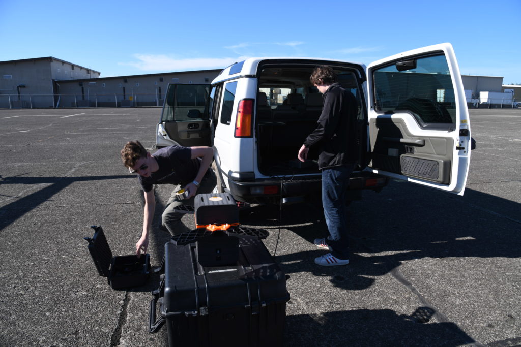
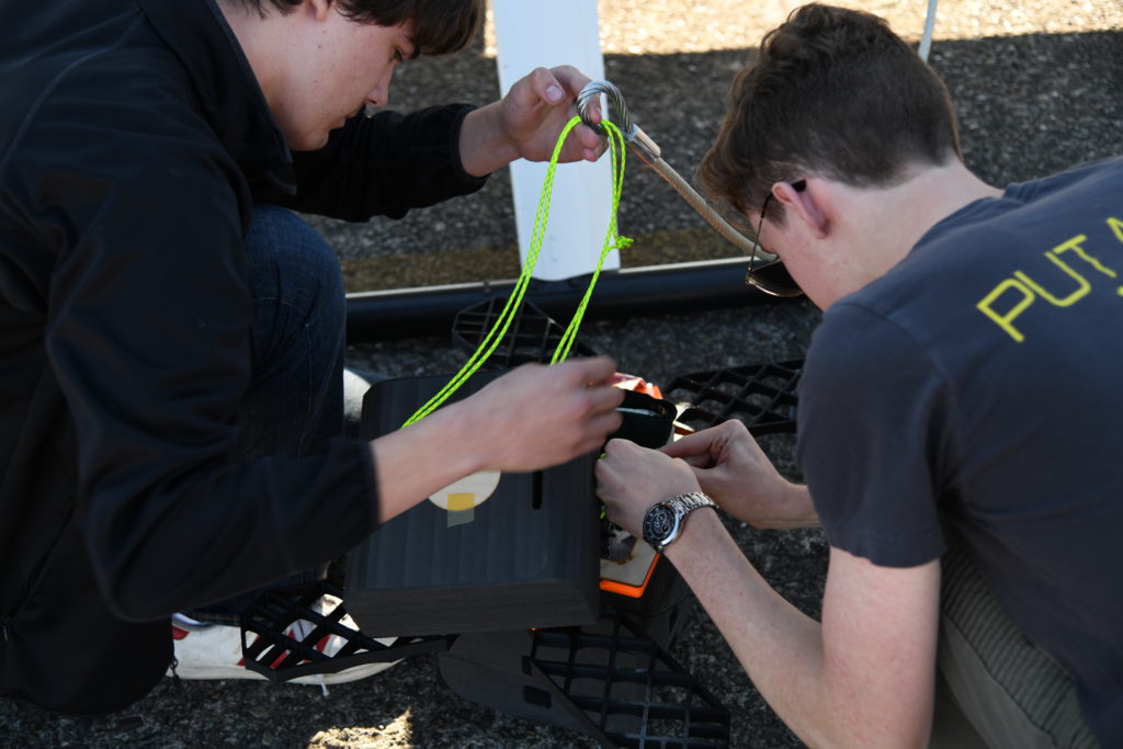
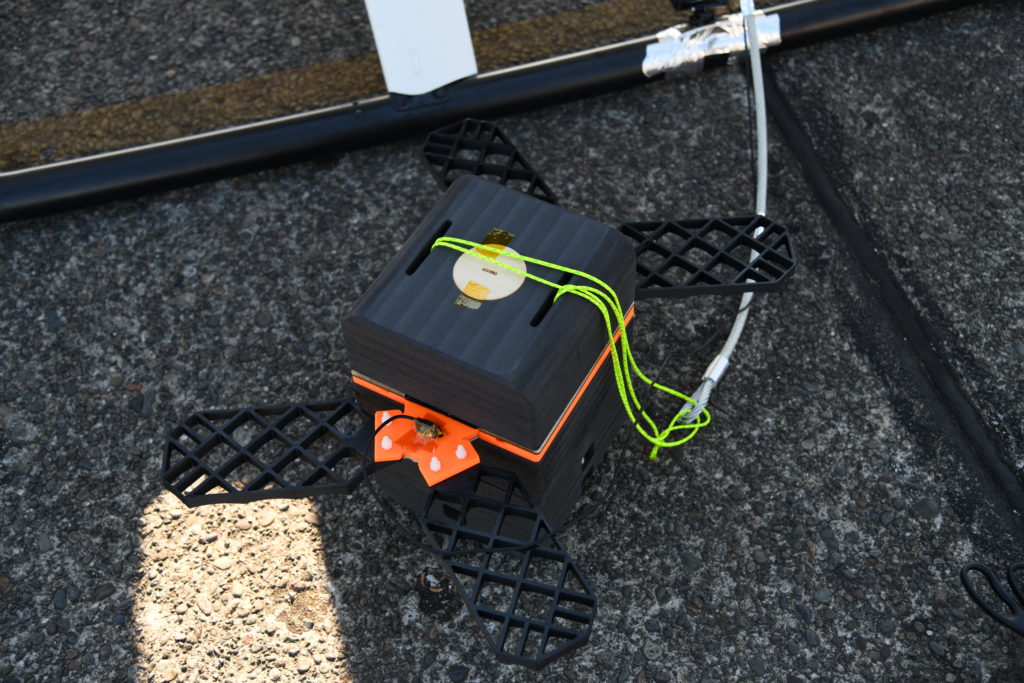
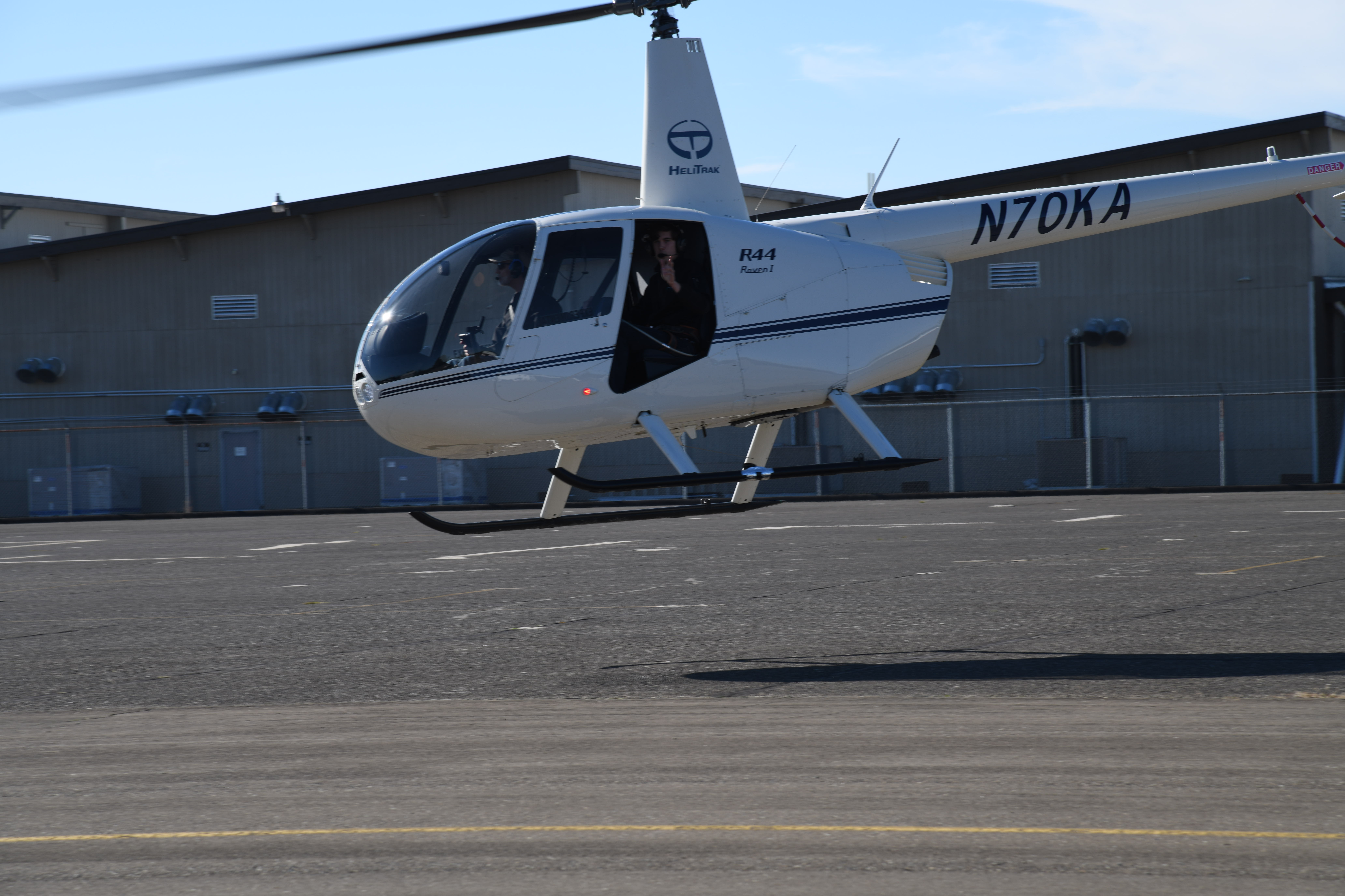
The pilot started the helicopter and immediately noticed that the integrated Garmin GPS wasn’t getting a solid lock. After a brief power-cycle, it (slowly) acquired a lock and off we went. The planned drop altitude was 4000 feet, and it took about 10 minutes to climb to altitude. Once there, skydiving traffic in the area delayed the drop for about 30 minutes.
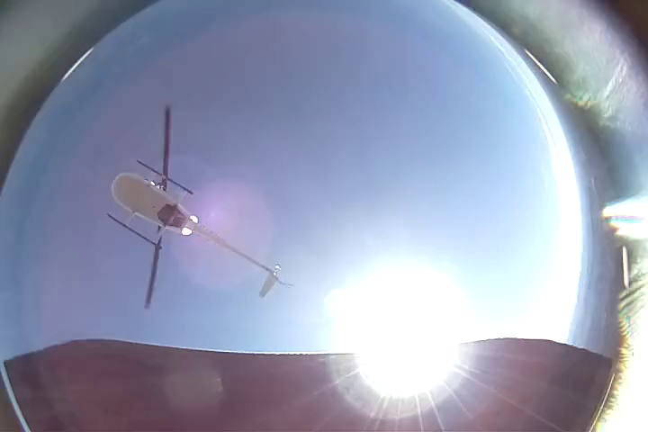
Sometime during this period, the downward facing GoPro we had mounted to the helicopter skid ran out of memory. It did capture a really cool image seconds before they payload began its descent
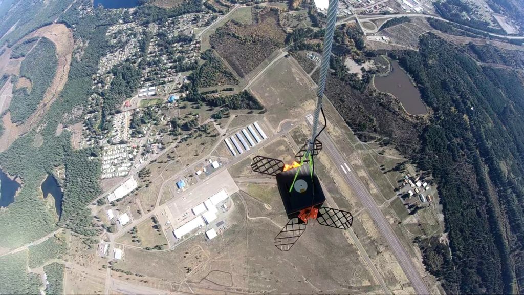
When we finally were given the all-clear, I armed the cutdown, and pushed both “fire” buttons on the RCI. Three agonizingly long seconds later, a loud bang signified a successful cutdown. I watched the payload cleanly separate from the lines and remain stable while passing through the helicopter’s wake.
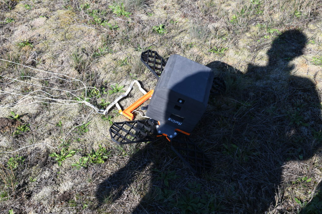
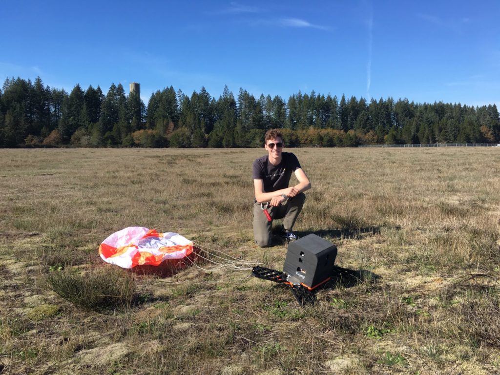
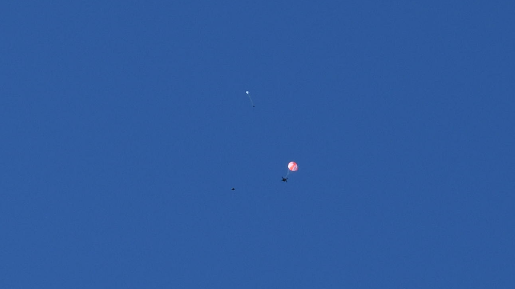
I was able to visually track the payload throughout freefall and main parachute deployment from the helicopter. It nailed the landing, touching down within 10 feet of the bush we were aiming for!
Drop Test Results
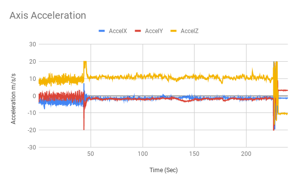
Most importantly, everything worked! All 4 cutdown pyros fired and the parachute deployed very close to the target altitude. The vehicle remained stable throughout free fall, slowly rotating without any coning or divergent oscillation – which was the primary concern for this test. Looking at the data, there are two very clear events: chute deployment and touchdown.
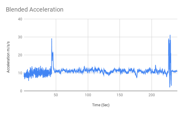
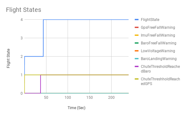
Flight states also progressed as planned, with Barometric Altitude triggering the parachute deployment, right on cue. Keep in mind the GPS could not trigger a chute deployment, based on the aforementioned problem.
One seemingly disappointing problem was that the upwards facing parachute camera stopped recording when the parachute pyro fired. This was determined to be a loose ribbon cable becoming dislodged. What was interesting is that immediately afterwards the GPS acquired a lock and began storing position data. After some sleuthing, it was discovered that the raspberry pi camera ribbon cable creates an enormous amount of interference when the camera is powered, basically acting as a wide-band signal jammer. It was powerful enough to interfere with the helicopters GPS as well! We had integrated the camera system a couple weeks before the drop test and hadn’t noticed that we began to experience GPS dropouts soon after. If the camera didn’t come unplugged in flight, I suspect it must have been much harder to diagnose the problem!
Avionics Block 2 Upgrade
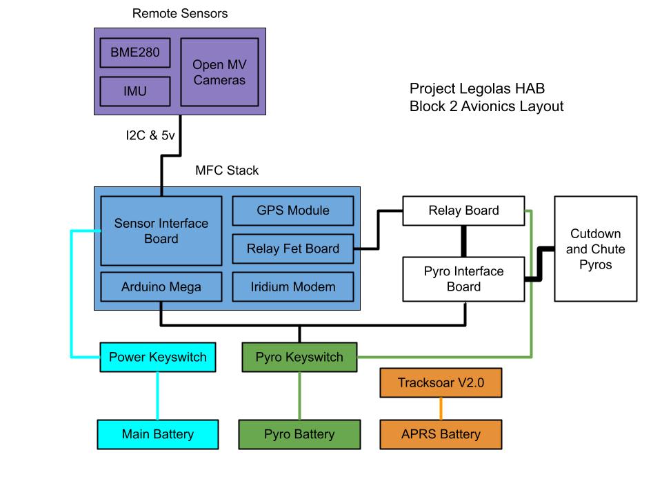
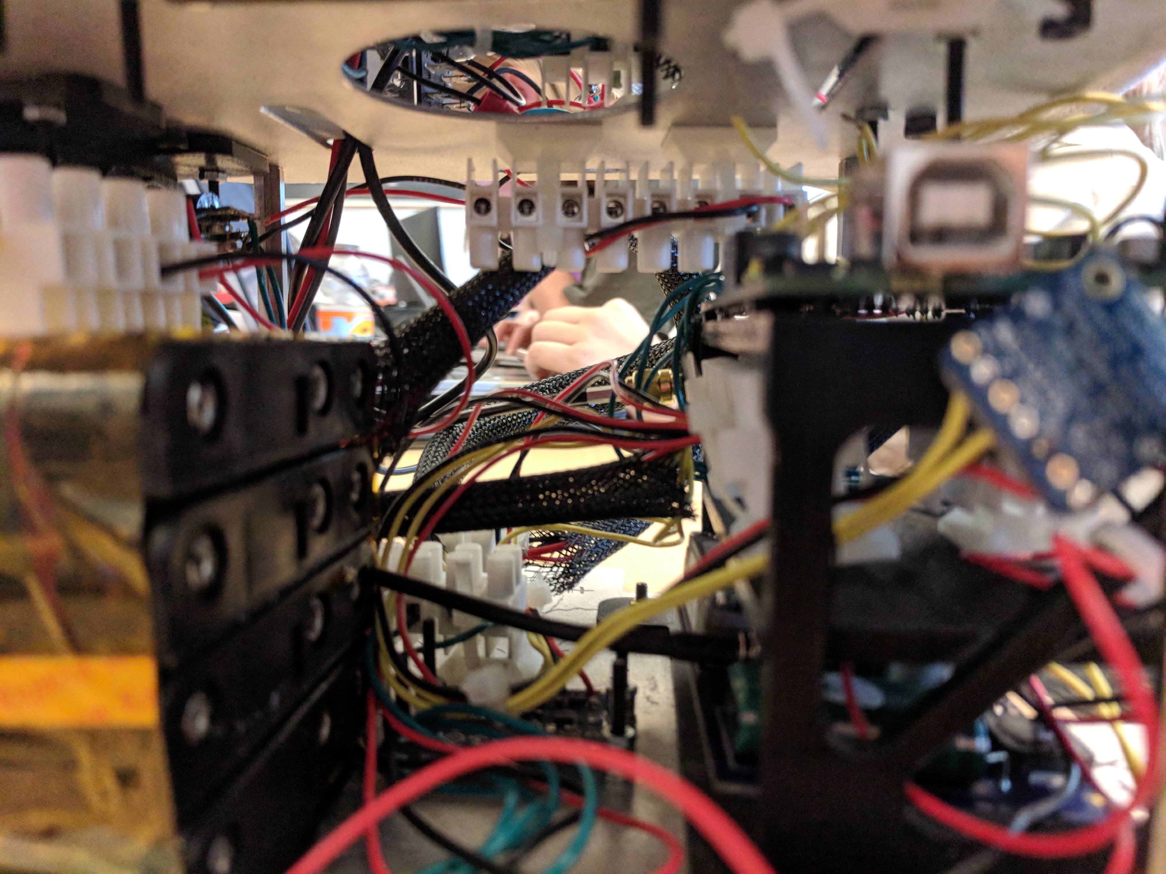
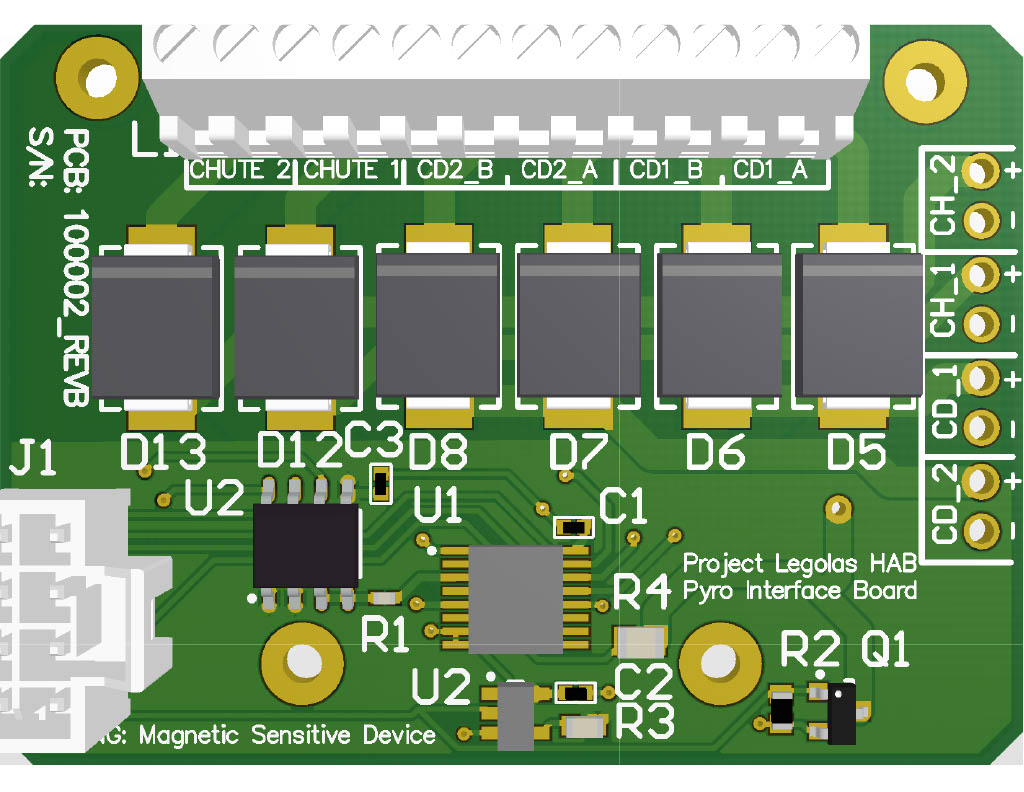
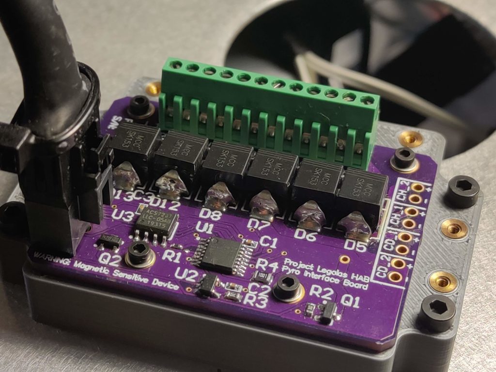
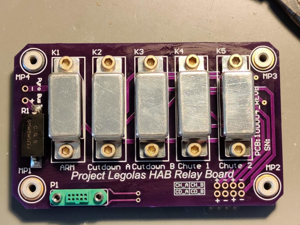
While the drop test configuration probably would have been fine to fly to near space on the balloon, I wanted to upgrade the avionics to a more robust state. Additionally, an alternate camera solution was needed, due to the interference problems encountered with the raspberry pis. This upgrade (aka Block 2) includes 4 new custom PCBs; A new relay driver board, upgraded hermetic relays, a new power supply, and an integrated Pyro continuity checker. Additionally, the Battery was upgraded to a 12v NiCad Battery, allowing an 8hr powered on time (version 4.5 was only 3 hours), and most of the wiring was upgraded to mil-spec quality. Finally, the IMU and avionics stack structure was upgraded, with blast shields being added to prevent damage from the pyros.
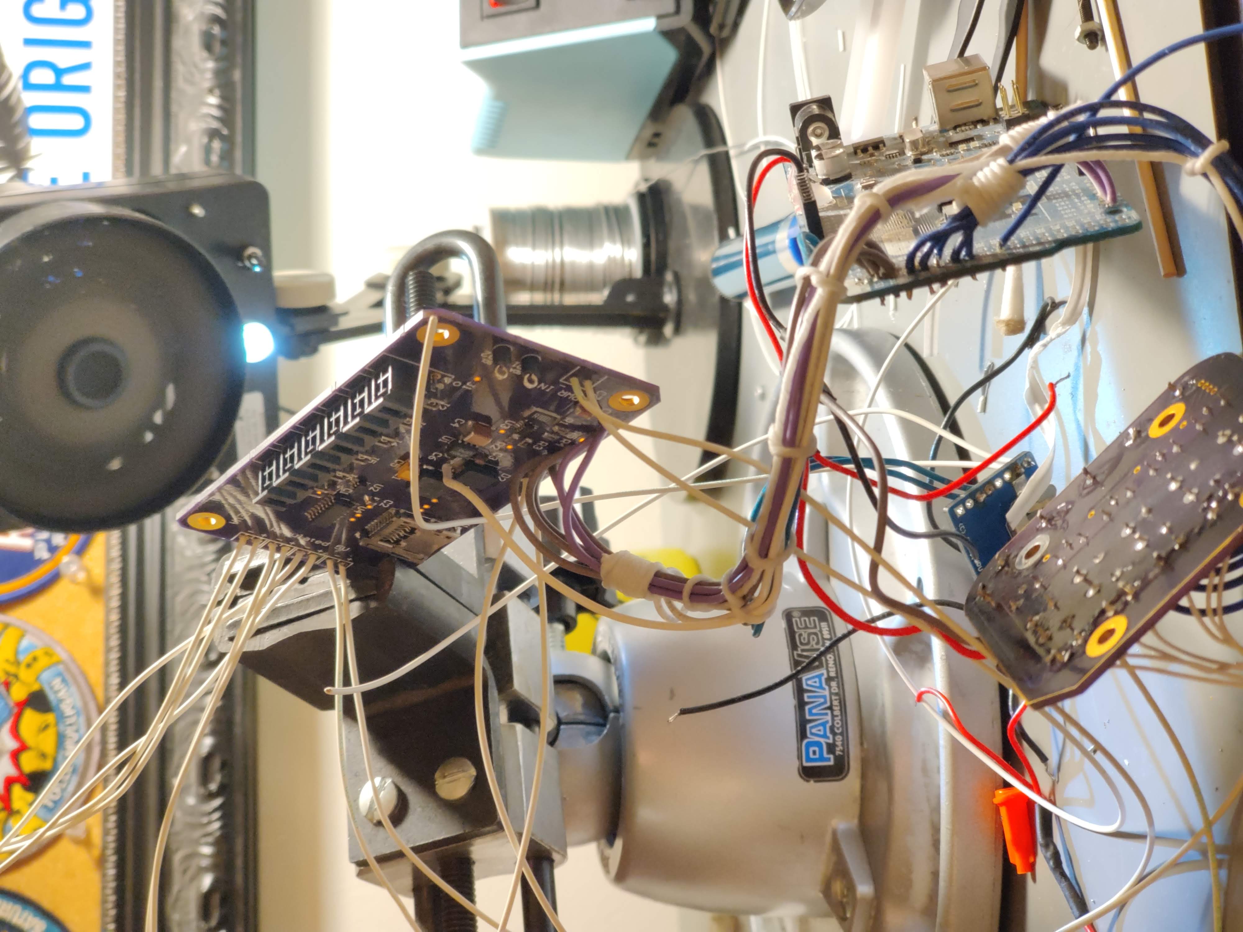
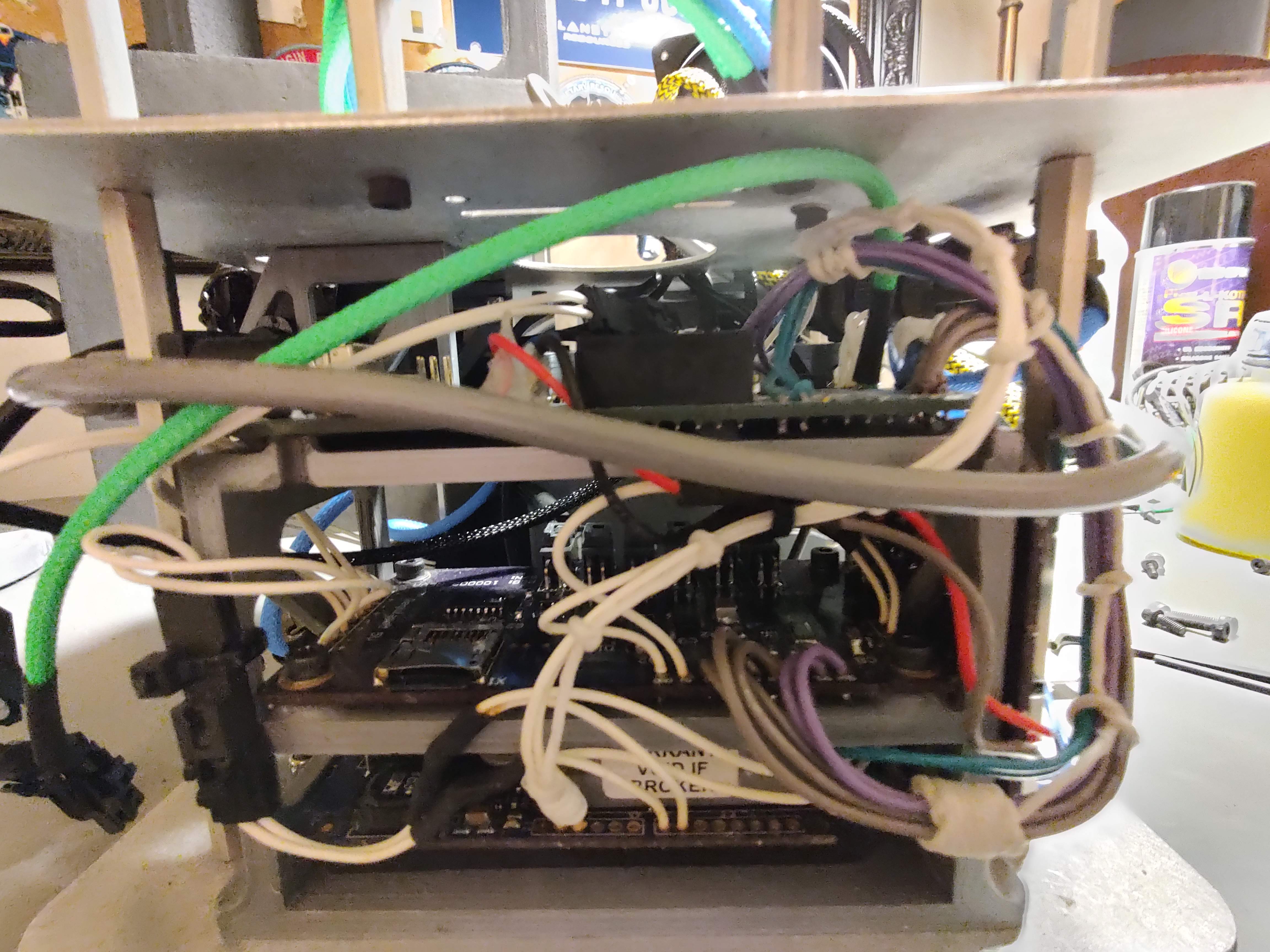
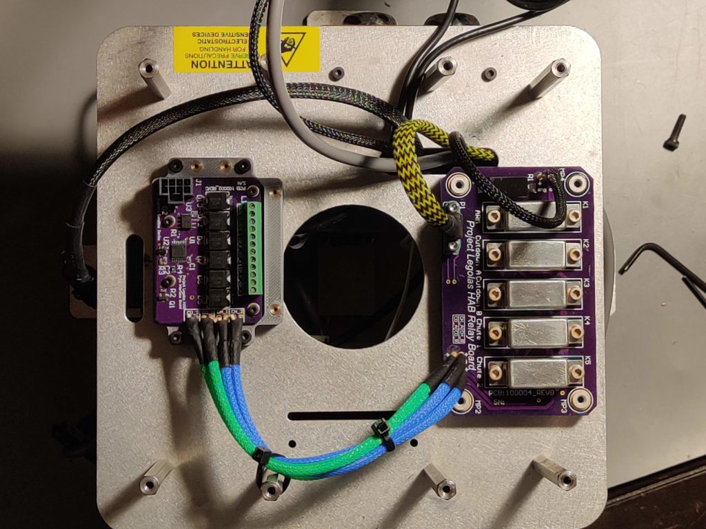
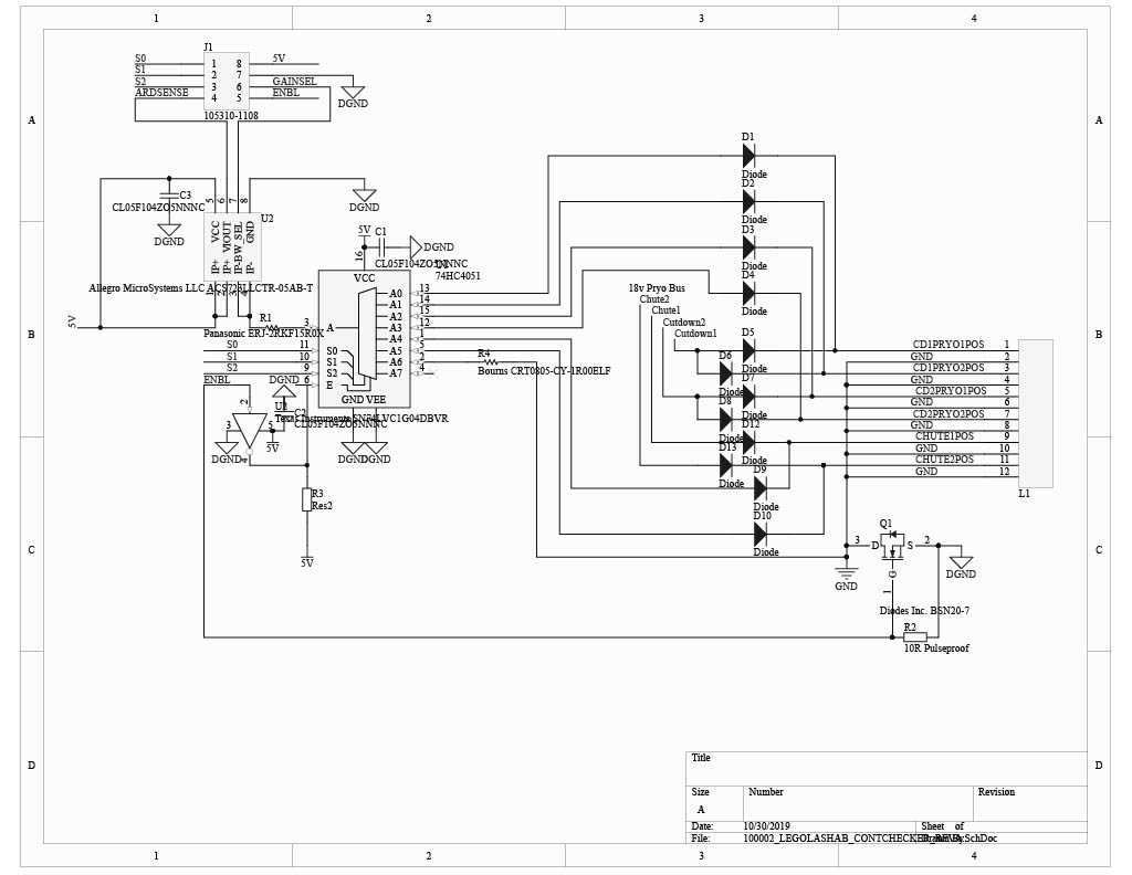
A feature I really wanted to add was the ability to check pyro continuity in an unobtrusive way. I devised a board that utilizes a current loop and hall effect sensor to read the resistance of each pyro individually, even when two are connected to one bus. A unique feature of this board is that the pyro and digital grounds are tied together only when continuity checking is in progress. This was based on the advice of a mentor and completely isolates the pyro from the avionics busses in flight, to ensure the absolute safety of the system.
Finally, the relays were upgraded from consumer grade to hermetic. This ensures that no moisture or ice can prevent the relays from working after the cold soak up to 120,000 feet.
Current Status
If you’re still with me after all that, thanks for reading! As of January 2021, the new cameras from OpenMV have arrived and are being installed in the payload. After that, a minor software upgrade will take place before flight 1. The plan is to launch once the weather improves around springtime. The planned launch site is Quincy, Washington, about 2 hours east of Seattle. I will definitely post updates to the blog and this page as we get closer!
– Cole

